
Technical Field
The present invention relates generally to railway safety systems and, more specifically, to a non-destructive structure-borne acoustic deterrent system and an artificial intelligence driven method for autonomously mitigating animal collisions on railway tracks while simultaneously generating infrastructure telemetry data and performing onboard structural diagnostics.
Background of the Invention
Collisions between rail vehicles and animals such as wildlife, livestock, or domestic species frequently result in significant animal suffering, material damage, and operational delays.
Although smaller animals may also be struck, the most severe incidents typically involve medium-sized and large mammals, including:
- Deer species
- Wild boar
- Moose
- Cattle
- Horses
Existing deterrent systems rely on airborne acoustic signals, such as train horns. However, these signals often fail for behavioral reasons.
Animals become habituated to vehicle horns and routinely observe both cars and trains passing without negative consequences. Because no natural predator moves at a comparable speed, animals frequently do not perceive an approaching train as an immediate threat and therefore fail to react until it is too late.
As a result, conventional acoustic warning systems do not consistently trigger effective avoidance behavior.
Existing structure-borne acoustic deterrent systems are limited to stationary installations mounted directly on railway infrastructure at specific high-risk locations.
Attempting to transfer this concept to a moving rail vehicle introduces significant mechanical challenges.
Mounting mechanical actuators to the sprung mass of a rail vehicle results in substantial energy losses through the vehicle’s primary and secondary suspension systems, greatly reducing acoustic transmission efficiency.
Rail vehicle suspension systems are specifically designed to isolate wheel-generated vibrations from the vehicle body, further limiting the propagation of structure-borne acoustic energy.
Existing systems also lack adaptability. Animals can rapidly habituate to static acoustic patterns, reducing long-term effectiveness.
Accordingly, there remains a need for a system capable of efficiently transmitting deterrent signals through railway infrastructure without compromising existing safety certifications, while also autonomously adapting to animal behavior and environmental conditions.
Summary of the Invention
The present invention addresses these challenges by generating a frightening sound that is perceived by the animal as originating from its immediate vicinity.
The sound is introduced into the rail through the wheel by means of a hermetically sealed mechanical impulse generator mounted on non-rotating unsprung components of a rail vehicle.
The system may be activated either by:
- A train driver
- An onboard control system
- An autonomous AI control unit
By coupling directly to the unsprung mass, the system utilizes:
- The non-rotating axle box
- Internal bearing assemblies
- The transverse wheel axle
- Rail wheels
as a continuous acoustic waveguide.
This structure enables long-range transmission of structure-borne acoustic shock waves directly into both load-bearing rails.
The generated waves produce both audible sound and tactile vibration that can be perceived by animals at substantial distances from the train.
Mounting the system on the sprung vehicle body would significantly attenuate the structure-borne signal due to suspension isolation. Therefore, mounting to the unsprung mass is essential.
An additional benefit of this arrangement is that the generated deterrent signal is prevented from propagating into the passenger compartment.
The system is designed for non-destructive installation, preserving existing safety approvals, certifications, and manufacturer warranties.
The impulse generator remains entirely within the dimensional envelope specified by EN 15273 and comparable national loading-gauge standards.
In at least one embodiment, the invention further comprises a comprehensive AI-driven operational framework.
The AI system is configured to:
- Detect biological entities
- Classify animal species
- Calculate dynamic Time-To-Collision (TTC) values
- Escalate deterrent stimuli when required
- Evaluate behavioral responses in real time
The system may additionally incorporate:
- Geospatial mapping
- Meteorological adaptation
- Predictive herd analysis
- Onboard structural diagnostics
- Large-scale telemetry generation
- Infrastructure optimization functions
Brief Description of the Drawings
The accompanying drawings, which form part of this specification, illustrate exemplary embodiments of the invention and, together with the detailed description, explain the mechanical, architectural, and operational principles of the system.
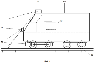
Figure 1
Figure 1 is a schematic side elevation view of a rail vehicle (100) positioned on a load-bearing rail (20).
The illustration shows the relative positioning of the primary system components, including:
- A forward-looking sensor module (50) mounted on the forward roof section
- A directed optical emitter (30) integrated into the vehicle nose
- An AI control unit (60) located within the passenger cabin
- A mechanical impulse generator (10) rigidly mounted to a non-rotating, unsprung axle box beneath the primary suspension system
Figure 2A
Figure 2A is a schematic frontal orthographic view facing a rail wheel hub.
The figure illustrates a first non-destructive retrofit embodiment in which the mechanical impulse generator (10) is integrated with, or attached to, a replacement axle-box end cover.
The assembly is mounted directly to a non-rotating axle-box housing (14) using an existing bolt pattern (22) without modifying the original structure.
Figure 2B
Figure 2B is a schematic side elevation view of a driven wheelset and gearbox assembly.
The illustration shows a second non-destructive mounting embodiment in which the mechanical impulse generator (10) is attached by means of a rigid mounting bracket (24) to a non-rotating gearbox housing (17) surrounding the transverse wheel axle (16).
Figure 2C
Figure 2C is a detailed transverse cross-sectional view of the wheelset and rail infrastructure.
The figure illustrates the continuous acoustic transmission path originating at the mechanical impulse generator (10) and propagating through:
- The non-rotating axle box (14)
- Internal bearing assemblies
- The transverse wheel axle (16)
- Rail wheels (18)
- Load-bearing rails (20)
The drawing further illustrates the direction of acoustic shockwave propagation through the metallic structure.
Figure 3
Figure 3 is a schematic side elevation view of a rail vehicle bogie.
The illustration demonstrates the mechanical isolation created by the primary suspension system positioned between the sprung vehicle body (100) and the unsprung axle boxes (14).
The figure further illustrates the transmission of acoustic shockwaves into the wheel (18) and subsequently into the rail (20).
Figure 4
Figure 4 is a comparative schematic diagram showing alternative encapsulation and connectivity configurations for the mechanical impulse generator (10).
The left side illustrates a wired embodiment comprising:
- Power and data connections
- Armored flexible conduit
- A dynamic U-shaped slack loop (12) designed to absorb suspension movement
The right side illustrates a wireless embodiment incorporating:
- Internal energy storage
- Kinetic energy harvesting module (13)
- IP68/IP69K protected enclosure (10)
Figure 5
Figure 5 is a functional block diagram illustrating the overall hardware architecture of the system.
The diagram shows power distribution and communication pathways between:
- Sensor module (50)
- Vehicle telematics interface (55)
- AI control unit (60)
- Power module (13)
- Mechanical impulse generator (10)
- Optical emitter (30)
The figure additionally illustrates the closed-loop feedback architecture used for outcome-based learning and adaptation.
Figure 6
Figure 6 is a process flowchart illustrating the operational methodology executed by the AI control unit (60).
The process includes:
- Biological entity detection
- Species classification
- Time-To-Collision (TTC) calculation
- Dynamic deterrent activation
- Stimulus escalation
- Flight-response verification
- Data logging
- Reinforcement-learning updates
Detailed Description of the Invention
5.1 Core System Architecture and Non-Destructive Paradigm
The invention provides a robust and commercially viable animal-deterrence system for railway applications.
At the core of the system is at least one mechanical impulse generator (10).
To withstand severe environmental conditions, including extreme winter weather, the impulse generator is housed within a hermetically sealed enclosure that isolates the internal components from ambient air.
This sealing prevents ingress of:
- Moisture
- Ice
- Dust
- Dirt
- Other contaminants
The enclosure may meet or exceed environmental protection standards such as:
- IP68
- IP69K
- Equivalent future standards
In some embodiments, the enclosure may additionally include integrated heating elements.
Unsprung-Mass Mounting Principle
A key aspect of the invention is the rigid coupling of the mechanical impulse generator (10) to the unsprung mass of the rail vehicle (100).
This arrangement maximizes mechanical transfer of acoustic energy into the wheelset and rail infrastructure.
The invention supports two principal implementation approaches:
Factory Integration (OEM)
In newly manufactured rail vehicles, non-rotating unsprung components may be produced with dedicated mounting interfaces for the impulse generator.
Examples include:
- Integrated mounting brackets
- Threaded attachment points
- Cast mounting flanges
- Dedicated fastening interfaces
These features may be incorporated directly during manufacture of the:
- Axle box (14)
- Gearbox housing (17)
- Other unsprung structural components
Aftermarket Retrofitting
For existing vehicle fleets, installation is preferably performed using strictly non-destructive mounting methods.
Within this specification, “non-destructive retrofitting” refers to installation methods that do not require:
- Drilling
- Welding
- Material removal
- Permanent structural modification
This approach preserves existing safety certifications, approvals, and manufacturer warranties.
Examples include:
- Utilizing existing bolt patterns (22)
- Replacing an axle-box end cover
- Mounting to existing gearbox interfaces
- Using form-fitting brackets (24)
- Attaching to existing structural ribs or cast features
These methods allow implementation without altering the certified structure of the rail vehicle.
5.2 Mechanical Acoustic Coupling
(See Figures 1, 2A-2C, and 3)
To achieve efficient propagation of structure-borne acoustic waves into the railway infrastructure, the invention utilizes the existing metallic structure of the rail vehicle as an acoustic waveguide.
As illustrated in Figures 2A-2C and Figure 3, the mechanical impulse generator (10) is not mounted to the vehicle chassis or bogie frame. Instead, it is mounted exclusively to an unsprung component of the vehicle.
In the preferred embodiment, the impulse generator (10) is rigidly bolted directly to the non-rotating axle box (14).
The axle box (14) houses the wheel bearing assemblies that support the rotating transverse wheel axle (16) and the rail wheels (18).
Because the axle box is located below the primary suspension system, it remains mechanically isolated from the passenger cabin and other sprung vehicle structures.
This arrangement allows the impulse generator to receive power and control signals without interference from rotating components.
Power and control signals may be delivered through:
- Electrical cables
- Pneumatic lines
- Hydraulic lines
- Wireless communication systems
all routed independently of rotating wheelset components.
Acoustic Energy Transmission Path
When an animal is detected on or near the railway track, either by the train operator or by the automated control system, an activation signal is generated.
Upon activation, the impulse generator (10) delivers mechanical impacts or vibrations directly into the axle box (14).
The generated mechanical energy propagates through a continuous metallic transmission path comprising:
- The axle box (14)
- Internal bearing assemblies
- The transverse wheel axle (16)
- Rail wheels (18)
- Both load-bearing rails (20)
The wheelset and rail assembly therefore function as a continuous acoustic waveguide.
Generation of Structure-Borne Shockwaves
The transmitted mechanical energy generates structure-borne acoustic shockwaves within the steel components.
These shockwaves travel through the rails at approximately the speed of sound in steel, typically around 5,000 meters per second.
This propagation speed is significantly greater than airborne sound, which travels at approximately 343 meters per second under normal atmospheric conditions.
As a result, animals located ahead of the rail vehicle may perceive the approaching stimulus much earlier than would be possible using conventional airborne warning systems.
Dual-Rail Transmission Effect
An important characteristic of the system is that the signal is coupled simultaneously into both load-bearing rails.
This creates a dual-track acoustic transmission pattern that extends forward along the railway infrastructure.
The resulting stimulus consists of:
- Audible acoustic emissions
- Ground-transmitted vibrations
- Tactile mechanical sensations
Together, these effects create a localized warning stimulus that is perceived by animals as originating directly from the track environment rather than from the approaching train itself.
Behavioral Advantage
Unlike conventional train horns, which are emitted from the train body and are often ignored due to habituation, the present invention creates the perception of a nearby and immediate threat.
Because the acoustic energy propagates through the track structure and surrounding ground, animals experience both sound and vibration in their immediate vicinity.
This significantly increases the likelihood of an avoidance response.
The warning stimulus therefore functions as:
- An auditory deterrent
- A tactile deterrent
- A spatially localized warning signal
capable of triggering flight behavior before the train reaches the animal.
Isolation from Passenger Areas
The mounting location below the suspension system provides a further advantage.
Because the impulse generator is coupled to the unsprung mass rather than the vehicle body, suspension components naturally attenuate the transmission of generated vibrations into passenger areas.
This allows high-energy deterrent signals to be introduced into the wheelset and rail system while minimizing the propagation of unwanted vibration and noise into:
- Passenger compartments
- Operator cabins
- Interior vehicle structures
Accordingly, the unsprung mounting arrangement simultaneously maximizes external deterrent effectiveness and minimizes internal acoustic disturbance.
5.3 Actuation Mechanisms and Broadband Frequency Paradigm
To provide effective deterrence across a wide range of biological species and environmental conditions, the hermetically sealed mechanical impulse generator (10) is configured to operate across an exceptionally broad frequency range extending from infrasonic frequencies to ultrasonic frequencies.
In a preferred embodiment, the operational frequency range extends from approximately:
1 Hz to 100 kHz
The generated output may comprise:
- Single-frequency signals
- Multi-frequency combinations
- Broadband shock pulses
- Continuous sinusoidal waveforms
- Frequency sweeps
- Phase-shifted noise signals
- Arrhythmic impact sequences
- Dynamically generated deterrent patterns
The impulse generator may be implemented using several alternative internal actuation technologies, each capable of converting electrical, pneumatic, hydraulic, or kinetic energy into high-amplitude structure-borne acoustic waves.
The embodiments described below are exemplary and non-limiting.
5.3 Actuation Mechanisms and Broadband Frequency Paradigm
To provide operational flexibility across a wide range of animal species and environmental conditions, the hermetically sealed mechanical impulse generator (10) is configured to operate across a broad frequency spectrum extending from infrasonic to ultrasonic frequencies.
In one embodiment, the operating range extends approximately from:
1 Hz to 100 kHz
The generated deterrent signals may comprise:
- Single-frequency signals
- Multi-frequency combinations
- Broadband transient shock pulses
- Continuous sinusoidal signals
- Frequency sweeps
- Dynamic phase-shifted noise
- Arrhythmic impact patterns
- Other dynamically generated acoustic signatures
The impulse generator may be implemented using several alternative actuation technologies configured to convert electrical, pneumatic, hydraulic, or kinetic energy into high-amplitude structure-borne acoustic waves.
The following embodiments are non-limiting examples.
5.3.1 Pneumatic and Hydraulic Transient Impact Hammer Embodiment
In a fluid-driven embodiment, the impulse generator (10) comprises a heavy-duty striking mass arranged within a sealed cylindrical chamber.
Compressed air may be supplied from:
- The primary braking reservoir
- An auxiliary pneumatic system
- An independent compressed-air source
Alternatively, hydraulic pressure may be utilized.
The working fluid is routed into the generator through high-speed control valves.
Upon receiving an activation signal from the AI control unit (60), the control valve rapidly pressurizes a drive chamber, accelerating the internal striking mass along a defined axis.
The striking mass impacts an internal anvil rigidly coupled to the exterior housing of the generator.
This impact generates a high-energy transient shockwave that is transmitted directly into the axle box (14) and subsequently into the wheelset and rail infrastructure.
After impact, the striking mass is returned to its starting position by means of:
- A spring mechanism
- Stored pneumatic energy
- Stored hydraulic energy
- Another return mechanism
This enables operation across a wide range of impact frequencies and patterns.
The system may generate:
- Single mechanical impacts
- Repetitive impact sequences
- Irregular impact rhythms
- High-energy warning bursts
The resulting acoustic signature may vary from sub-Hertz repetition rates to multi-kilohertz harmonic structures.
5.3.2 Electrodynamic Linear Actuator and Solenoid Impactor Embodiment
In an electrically driven embodiment, the impulse generator incorporates an electrodynamic linear actuator or a heavy-duty electromagnetic striker.
The actuator may include:
- A ferromagnetic plunger
- A magnetic armature
- One or more electromagnetic coils
- An acoustic transfer plate
When activated, a high-current electrical pulse supplied by the power module (13) energizes the coil assembly.
The resulting magnetic field rapidly accelerates the plunger toward the acoustic transfer interface.
The generated impact energy is transferred directly into the non-rotating unsprung structure supporting the generator.
The AI control unit (60) may dynamically regulate:
- Pulse duration
- Current amplitude
- Strike force
- Repetition frequency
This allows continuous adjustment of acoustic output over the operational frequency range.
The control strategy enables generation of highly variable acoustic signatures designed to prevent long-term habituation by wildlife.
Examples include:
- Randomized impact series
- Frequency-shifted patterns
- Species-specific acoustic profiles
- Environment-dependent warning sequences
5.3.3 Piezoelectric Stack Transducer Embodiment
In a solid-state embodiment optimized for high-frequency operation, the impulse generator utilizes a piezoelectric stack transducer or a magnetostrictive actuator.
The active element may be mechanically preloaded between:
- An internal reaction mass
- The generator baseplate
Upon application of electrical excitation signals, the piezoelectric stack undergoes rapid microscopic expansion and contraction.
These dimensional changes create high-force acoustic stress waves that are transferred directly into the surrounding metallic structure.
Because the actuator contains few or no conventional moving mechanical parts, the embodiment offers:
- High reliability
- Low maintenance requirements
- Fast response times
- Precise frequency control
This embodiment is particularly suited for:
- High-frequency structure-borne excitation
- Rail resonance stimulation
- Ultrasonic acoustic emission
Typical operating ranges may extend from approximately:
1 kHz to 100 kHz
The generated signals can propagate efficiently through continuous welded rail and other metallic track structures.
5.3.4 Electrodynamic Shaker and Eccentric Rotating Mass (ERM) Embodiment
In another embodiment, the impulse generator comprises either:
- A heavy-duty electrodynamic shaker
- A voice-coil tactile transducer
- A motor-driven eccentric rotating mass (ERM)
The ERM configuration creates periodic mechanical forces through controlled rotational imbalance.
The voice-coil configuration drives an internal mass along a linear axis using controlled electrical excitation signals.
The generated output may consist of:
- Sinusoidal waveforms
- Broadband noise
- Frequency-modulated signals
- Arbitrary waveforms
- Swept-frequency signals
Operating frequencies may range from approximately:
1 Hz to 20 kHz
This approach enables continuous acoustic excitation of the rail infrastructure rather than discrete impact generation.
By sweeping through structural resonance frequencies within:
- The axle box
- The wheelset
- The rails
the system can maximize acoustic transmission efficiency and increase the effectiveness of the deterrent signal.
The resulting structure-borne acoustic energy may radiate into the surrounding terrain as audible sound, vibration, or a combination thereof, thereby increasing the probability of eliciting an avoidance response from nearby animals.
5.4 Encapsulation and Environmental Tolerance
To ensure reliable operation under severe railway environmental conditions, the mechanical impulse generator (10) is housed entirely within a heavy-duty hermetically sealed enclosure.
The enclosure protects internal components from exposure to:
- Water
- Snow
- Ice
- Dirt
- Salt
- Dust
- Railway debris
Because the internal mechanisms are isolated from ambient air, operation is largely unaffected by external contamination or ice accumulation.
The enclosure may be designed to comply with demanding railway environmental requirements and high ingress-protection classifications.
Housing materials and internal tolerances may be selected to accommodate:
- Thermal expansion
- Thermal contraction
- Repeated freeze-thaw cycles
- Mechanical shock
- Continuous vibration
The enclosed design enables long-term operation across extreme climatic conditions while preserving reliability and minimizing maintenance requirements.
5.4 Encapsulation and Environmental Tolerance
To ensure reliable operation under the demanding environmental conditions encountered in railway service, the mechanical impulse generator (10) is housed within a robust hermetically sealed enclosure.
The enclosure is designed to completely isolate internal components from the external environment, preventing intrusion of:
- Water
- Snow
- Ice
- Dust
- Sand
- Road and rail debris
- Salt contamination
- Other airborne particulates
Because the internal mechanisms operate within a sealed environment, system performance is not significantly affected by external ice accumulation or contamination.
This design is particularly advantageous in regions exposed to severe winter conditions, where traditional exposed mechanical systems may suffer from freezing, blockage, or accelerated wear.
Environmental Protection
In preferred embodiments, the enclosure is designed to comply with high-level ingress protection standards, including:
- IP68
- IP69K
- Equivalent future environmental standards
Such protection ensures continued operation during exposure to:
- Heavy rainfall
- Snowstorms
- Flooding
- High-pressure cleaning procedures
- Dust-intensive operating environments
Mechanical Durability
The enclosure is further designed to withstand:
- Continuous vibration
- Mechanical shock
- Track irregularities
- Rapid acceleration and deceleration forces
- Long-term operational fatigue
Materials used in the enclosure may include:
- Stainless steel
- High-strength aluminum alloys
- Corrosion-resistant steel
- Advanced engineering polymers
- Composite materials
or combinations thereof.
Thermal Stability
Rail vehicles frequently operate across extreme temperature ranges.
Accordingly, enclosure geometry and material selection may be optimized to accommodate:
- Thermal expansion
- Thermal contraction
- Freeze-thaw cycles
- Rapid environmental temperature transitions
without compromising sealing integrity or mechanical performance.
Internal Heating
In some embodiments, the impulse generator (10) may incorporate an internal heating system.
The heating system may be configured to:
- Maintain operational temperature ranges
- Prevent condensation
- Reduce internal humidity
- Improve startup reliability during extreme cold conditions
The heating function may operate:
- Continuously
- Periodically
- On demand
- Automatically based on temperature measurements
Dimensional Compliance
Despite its environmental protection features, the enclosure is designed to remain within the permissible spatial limits of the rail vehicle.
The system therefore does not extend beyond the vehicle envelope defined by:
- EN 15273
- Equivalent national loading-gauge standards
- Applicable railway clearance regulations
This enables installation without adversely affecting infrastructure compatibility or vehicle certification requirements.
Long-Term Reliability
The combination of hermetic sealing, environmental protection, mechanical robustness, and thermal management enables long-term operation with minimal maintenance requirements.
As a result, the impulse generator (10) remains capable of delivering reliable acoustic deterrent performance throughout prolonged railway service under a wide range of climatic and operational conditions.
5.5 Universal Mounting Examples
Because railway vehicles utilize a wide variety of bogie, axle, and gearbox configurations, the present invention includes multiple non-destructive mounting approaches suitable for different vehicle architectures.
The mounting solutions are designed to maintain:
- Structural integrity
- Safety certification compliance
- Serviceability
- Acoustic transmission efficiency
while avoiding permanent modifications to the host vehicle.
Example A: End-Cover Replacement (Figure 2A)
In one embodiment, the mechanical impulse generator (10) is integrated into a replacement axle-box end cover.
The replacement component utilizes the existing bolt pattern (22) already present on the axle-box housing (14).
This arrangement allows installation without:
- Drilling
- Welding
- Machining
- Structural modification
The replacement cover provides a compact and mechanically efficient mounting solution while maintaining the external dimensions of the original assembly.
Advantages include:
- Simple installation
- Direct acoustic coupling
- Preservation of certification status
- No increase in vehicle width
Example B: Gearbox-Housing Mounting for Driven Axles (Figure 2B)
Many locomotives and powered bogies employ driven wheelsets equipped with gearbox assemblies.
In these vehicles, the gearbox housing (17) forms part of the non-rotating unsprung mass surrounding the transverse wheel axle (16).
In this embodiment, the impulse generator (10) is secured to the gearbox housing using:
- Existing mounting points
- Existing bolt patterns
- Form-fitting brackets (24)
- Dedicated adapter structures
The cast-metal gearbox structure serves as an efficient acoustic transfer medium.
Mechanical impulses generated by the device propagate through:
- The gearbox housing (17)
- The wheel axle (16)
- The rail wheels (18)
- The rails (20)
This embodiment allows effective implementation on powered wheelsets without modification of critical drivetrain components.
Example C: Inboard Bearing Mounting for Modern Rail Vehicles
Certain modern rail vehicles employ wheelsets with inboard bearings.
In such arrangements, the axle box (14) is positioned between the wheels (18) beneath the vehicle frame.
In this embodiment, the impulse generator (10) is mounted directly to the inboard axle box.
This configuration offers several benefits.
Enhanced Mechanical Protection
The location provides natural protection against:
- Side impacts
- Flying ballast
- Snow accumulation
- Environmental debris
Reduced Aerodynamic Exposure
Because the device is positioned closer to the vehicle centerline, aerodynamic loading is reduced compared with externally exposed installations.
Optimized Acoustic Coupling
The location maintains a direct metallic transmission path through:
- The axle box (14)
- Bearing assemblies
- The transverse wheel axle (16)
- Rail wheels (18)
- The rails (20)
This ensures efficient transfer of acoustic energy into the railway infrastructure.
Adaptability to Vehicle Fleets
The mounting examples described above are intended as representative implementations.
Other mounting arrangements may be utilized provided that the impulse generator remains mechanically coupled to a non-rotating unsprung structure capable of transmitting structure-borne acoustic energy into the wheelset and rail system.
Accordingly, the invention may be adapted to a broad range of:
- Passenger trains
- Freight wagons
- Locomotives
- High-speed trains
- Light rail vehicles
- Maintenance vehicles
- Specialized rail equipment
without departing from the scope of the invention.
5.6 Power and Signal Routing / Wireless Implementation
The mechanical impulse generator (10) may be implemented using either a wired architecture, a wireless architecture, or a hybrid combination thereof.
The selected architecture may depend on:
- Vehicle design
- Retrofit requirements
- Maintenance preferences
- Power availability
- Fleet-specific operational considerations
Wired Implementation
In a wired embodiment, electrical power and control signals are transferred from the sprung portion of the rail vehicle to the unsprung impulse generator (10).
Because the generator is mounted below the primary suspension system, all cables must traverse the suspension zone while accommodating continuous relative movement between the sprung and unsprung masses.
To prevent fatigue and mechanical damage, power and communication lines are preferably enclosed within:
- Armored flexible conduits
- Reinforced cable ducts
- Protective hose assemblies
The conduit is routed through a designated flexible slack-loop section (12).
The slack loop absorbs suspension travel and allows uninterrupted operation despite:
- Vertical wheel movement
- Dynamic bogie motion
- Track irregularities
- Vehicle vibration
This arrangement reduces long-term mechanical stress on conductors and hoses while maintaining reliable communication and power delivery.
Wireless and Self-Sustaining Implementation
In an alternative embodiment, the impulse generator (10) operates as an autonomous wireless unit.
The generator includes:
- Local energy storage
- Power management electronics
- Wireless communications hardware
- Energy-harvesting systems
The energy-harvesting system may derive power from:
- Wheelset vibration
- Axle vibration
- Rotational energy
- Suspension movement
- Other kinetic energy sources associated with rail vehicle operation
Harvested energy is stored locally and used to power both electronics and acoustic actuation systems.
Wireless Communication
In the wireless embodiment, activation commands are transmitted from the AI control unit (60) without requiring physical signal cables.
Communication may be performed using:
- Radio-frequency communication
- Bluetooth
- Wi-Fi
- Cellular communication
- 5G communication
- Future wireless communication technologies
Secure communication protocols may be employed to ensure reliable operation and resistance to interference.
Advantages of Wireless Operation
The wireless embodiment eliminates physical connections crossing the suspension system.
This provides several advantages, including:
- Simplified installation
- Reduced maintenance requirements
- Elimination of cable fatigue
- Easier retrofit implementation
- Reduced mechanical complexity
The wireless architecture is particularly advantageous for retrofit installations where routing new cables may be difficult or costly.
5.7 Advanced Sensor Integration, Dynamic Triggering, and Manual Override
The system is further characterized by advanced sensor integration and autonomous decision-making capabilities.
In a fully autonomous embodiment, activation of the deterrent system is controlled by the AI control unit (60) using information obtained from a forward-looking sensor module (50).
Sensor Module
The sensor module (50) is mounted on a forward-facing section of the rail vehicle (100).
The module may utilize sensor-fusion techniques that combine data from multiple sensor types.
Examples include:
- Optical cameras
- Thermal imaging cameras
- Radar systems
- LiDAR systems
- Infrared sensors
- Distance-measurement sensors
The use of multiple sensing modalities improves reliability under varying environmental conditions.
Biological Entity Detection
The sensor module continuously monitors the railway corridor ahead of the vehicle.
When a biological entity is detected on or near the track area, the collected sensor data is transmitted to the AI control unit (60) for analysis.
The system may identify:
- Wildlife
- Livestock
- Domestic animals
- Groups of animals
- Other biological entities
Dynamic Time-To-Collision Calculation
The AI control unit receives vehicle speed data from the telematics interface (55).
Using position, distance, and speed information, the system continuously calculates a dynamic Time-To-Collision (TTC) value.
The calculated TTC enables determination of an optimal activation point for the deterrent sequence.
The objective is to ensure that the animal receives:
- Sufficient warning time.
- Sufficient processing time.
- Sufficient movement time.
This approach allows effective operation across a broad range of train speeds.
Intelligent Trigger Distance
Unlike fixed-distance activation systems, the present invention dynamically adjusts activation distance based on real-time operating conditions.
Parameters that may influence trigger distance include:
- Train speed
- Animal position
- Animal movement direction
- Species classification
- Environmental conditions
- Historical behavioral data
As a result, the deterrent sequence is initiated at the most appropriate moment for maximizing avoidance behavior.
Manual Override
To comply with railway safety principles and provide operational flexibility, the system includes a manual override interface accessible to the train operator.
The interface may be implemented as:
- A physical control
- A touch-screen interface
- A cab-mounted control panel
- A software interface
The operator may at any time:
- Activate the deterrent system
- Disable the deterrent system
- Escalate a deterrent sequence
- Select an alternative deterrent profile
Safety Priority
The manual override function ensures that human operators retain ultimate control of the system.
This arrangement allows the deterrent technology to operate autonomously while remaining compatible with existing railway safety and operational procedures.
5.8 Biological Profiling and Adaptive Deterrent Escalation
The AI control unit (60) utilizes machine-learning models and neural-network based classification systems to analyze detected animals.
Upon detection of a biological entity, the system generates a biological profile describing the characteristics of the animal.
Species Classification
The classification process may determine:
- Species
- Estimated size
- Body proportions
- Movement characteristics
- Other identifiable biological traits
Examples include:
- Cervids
- Cattle
- Horses
- Canines
- Wild boar
- Other wildlife species
Secondary Biological Characteristics
The system may also identify characteristics that influence behavioral response.
Examples include:
- Presence of antlers
- Absence of antlers
- Estimated age
- Group behavior
- Physical condition
These observations may provide additional insight into likely animal reactions.
Deterrent Profile Selection
Based on the generated biological profile, the AI control unit selects an optimized deterrent profile.
A deterrent profile may comprise a configurable combination of:
- Acoustic frequencies
- Impulse amplitudes
- Impact timing
- Rhythmic patterns
- Optical stimuli
- Airborne acoustic signals
The initial profile is selected according to known effectiveness for a particular animal category.
Adaptive Escalation
Following activation, the sensor module (50) continuously evaluates the animal’s response.
If the animal remains within the railway clearance envelope or fails to exhibit avoidance behavior, the system enters an escalation phase.
During escalation, the AI may dynamically modify one or more deterrent parameters, including:
- Increasing impulse energy
- Altering frequencies
- Introducing arrhythmic patterns
- Changing pulse repetition rates
- Activating supplementary deterrent systems
- Combining multiple deterrent modalities
Closed-Loop Behavioral Control
The escalation process continues until the system verifies one of the following outcomes:
- The animal has initiated flight behavior.
- The animal has left the track area.
- The risk level has decreased below a defined threshold.
This closed-loop approach enables the deterrent strategy to adapt in real time to the observed behavior of individual animals rather than relying solely on predetermined warning patterns.
5.9 Multi-Sensory Supplementary Deterrents
In situations where structure-borne acoustic signals alone are insufficient due to environmental conditions, species-specific behavior, or elevated stress thresholds, the system may deploy one or more supplementary deterrent modalities under the control of the AI control unit (60).
These supplementary deterrents may operate independently or in combination with the structure-borne acoustic warning system.
Headlight Dimming Mechanism
Certain animal species, particularly cervids such as deer and moose, may exhibit a light-induced freeze response when exposed to bright headlights.
To mitigate this behavior, the AI control unit (60) may be communicatively connected to the vehicle’s lighting control system.
Upon detection of an animal, the control unit may temporarily reduce headlight intensity by switching from main beam to dipped beam for a predetermined interval.
Typical activation periods may range from:
- 1 second
- 2 seconds
- 3 seconds
- Other configurable durations
This temporary reduction in illumination may improve the animal’s ability to regain visual orientation and initiate escape behavior.
Optical Deterrent Device
The system may further incorporate a directed optical emitter (30).
The optical emitter may comprise:
- High-intensity LED arrays
- Multi-spectrum LED systems
- Laser projection systems
- Dynamic optical pattern generators
The emitter projects rapidly changing visual stimuli into the area ahead of the train.
Examples include:
- Moving light patterns
- Irregular flashes
- Directional light sweeps
- Dynamic optical signatures
The objective is to trigger instinctive avoidance behavior without relying solely on color perception.
Airborne Acoustic Deterrent
The system may additionally employ directional airborne sound generators.
Examples include:
- LRAD systems
- Directional loudspeakers
- High-output acoustic emitters
These devices may broadcast:
- Predator sounds
- Dog barking
- Species-specific warning calls
- Synthetic alert signals
- Other deterrent sounds
The airborne acoustic signals complement the structure-borne vibrations generated through the rail system.
Activation may occur:
- Automatically by the control unit
- Manually by the driver
- Through predefined operating modes
This approach provides an alternative to conventional train horn operation.
Predator Visual Cue
In at least one embodiment, the front of the rail vehicle may display a graphical representation of a predator.
Examples include:
- A predator head
- Large predator eyes
- Species-specific threat imagery
- Other biologically relevant visual cues
The visual cue is intended to enhance the natural perception of an approaching threat and amplify the effectiveness of the acoustic deterrent system.
When combined with structure-borne and airborne warning signals, the visual stimulus may contribute to a more immediate flight response.
Projectile-Based Deterrent with Reaction-Time Logic
In at least one embodiment, the rail vehicle may include a projectile-based deterrent system intended for use as a last-resort measure.
The system may be mounted on the front section of the rail vehicle and configured to launch less-lethal projectiles in the direction of travel.
Examples include:
- Paintballs
- Rubber balls
- Other low-energy impact projectiles
The launcher assembly may include:
- A barrel
- A firing mechanism
- A feeding system
using technologies known from paintball markers and less-lethal launchers.
Aiming and Control
The launch direction may be:
- Fixed
- Vertically adjustable
- Horizontally adjustable
- Fully automated
Adjustment may be performed using electrically driven actuators controlled by:
- The train operator
- The onboard control unit
- Both systems in combination
Automated Firing Logic
The onboard control unit may automatically:
- Detect the animal
- Estimate distance
- Determine animal position
- Calculate firing timing
- Predict projectile trajectory
The firing calculation may take into account:
- Train speed
- Projectile velocity
- Animal location
- Estimated reaction time
The objective is to ensure that the animal receives sufficient warning and reaction time prior to the arrival of the train.
Adaptive Engagement
If the animal does not respond to previously deployed deterrents, the system may fire one or more projectiles until escape behavior is observed.
The projectile-based system is intended as a supplementary measure when prior deterrent stages have failed to remove the animal from the track area.
The deterrent may be activated:
- Automatically by the AI control unit (60)
- By a driver-operated trigger
- Through predefined emergency operating modes
Multi-Modal Escalation Strategy
The supplementary deterrent systems described above may operate as part of a coordinated escalation framework.
Based on observed animal behavior, the AI control unit may dynamically combine:
- Structure-borne acoustic warnings
- Airborne acoustic warnings
- Optical deterrents
- Lighting modifications
- Projectile-based deterrents
The deterrent strategy may be continuously modified until the animal leaves the danger zone or the collision risk has been reduced below a predefined threshold.
5.10 Reinforcement Learning and the Feedback Loop
A fundamental aspect of the invention is its continuous empirical learning capability.
The AI control unit (60) employs an adaptive machine-learning architecture that may incorporate:
- Reinforcement learning
- Supervised learning
- Unsupervised learning
- Hybrid learning frameworks
The system establishes a continuous feedback loop between observed animal behavior and future deterrent decisions.
During and after each animal encounter, the sensor module (50) monitors and records the result of the intervention.
Examples of recorded outcomes include:
- Immediate flight response
- Delayed flight response
- Partial avoidance behavior
- Repeated exposure
- Collision events
For each event, the system stores the exact combination of deterrent parameters that were applied.
Recorded parameters may include:
- Acoustic frequencies
- Impulse amplitudes
- Timing sequences
- Optical stimuli
- Airborne acoustic signals
- Escalation strategies
The accumulated data is analyzed to determine which combinations produce the highest probability of successful avoidance behavior.
Over time, the AI continuously refines and optimizes deterrent profiles based on real-world observations.
This enables the system to improve its effectiveness through operational experience while adapting to:
- Regional wildlife populations
- Species-specific behavior
- Seasonal variations
- Environmental conditions
- Infrastructure characteristics
The feedback loop therefore transforms each animal encounter into additional training data that contributes to ongoing system improvement
5.11 Predictive Herd Dynamics and Offspring Tracking
The AI control unit (60) is configured to analyze herd dynamics and behavioral patterns based on the biological characteristics of detected animals.
In addition to evaluating the primary animal, the system assesses the probability that additional animals may be present nearby.
Biological and Behavioral Analysis
The AI may utilize observed characteristics including:
- Species identification
- Body size
- Movement behavior
- Grouping patterns
- Presence or absence of antlers
- Morphological features
- Seasonal behavioral indicators
These observations are used to infer the likelihood of associated animals being present within the railway corridor.
Offspring Prediction
For example, when the system identifies a female animal, the AI may estimate the probability that offspring are nearby.
Examples include:
- Moose calves
- Deer fawns
- Wild boar piglets
- Other juvenile animals
Because juveniles frequently trail behind adult animals, the departure of the primary animal does not necessarily eliminate the collision risk.
Adaptive Response
When offspring presence is considered likely, the system may automatically:
- Extend the deterrent sequence duration
- Increase monitoring time
- Expand the sensor observation area
- Continue scanning after the primary animal leaves the track area
The sensor module (50) may also increase sensitivity to smaller biological entities that could otherwise remain undetected.
Enhanced Safety
By predicting herd behavior and family-group movement patterns, the system reduces the risk that secondary animals enter or remain within the danger zone after the initial threat appears to have been resolved.
5.12 Geospatial Intelligence and Habituation Mitigation
To mitigate long-term habituation effects, the AI control unit (60) may be connected to a positioning system through the telematics module (55).
The system continuously associates deterrent outcomes with geographical locations.
Geographic Learning Database
The AI maintains a location-specific effectiveness model that links deterrent performance to:
- GPS coordinates
- Species information
- Environmental conditions
- Historical outcomes
This enables continuous adaptation to regional wildlife populations.
Habituation Recognition
Certain wildlife populations may become accustomed to specific stimuli over time.
Examples may include populations living near:
- Military training facilities
- Artillery ranges
- Mining operations
- Industrial sites
- Other high-noise environments
In such areas, conventional acoustic stimuli may become less effective.
Location-Based Adaptation
When the train enters a region associated with reduced effectiveness of certain deterrent methods, the AI may automatically modify the deterrent strategy.
Examples include:
- Increasing use of predator calls
- Increasing use of optical deterrents
- Altering frequency content
- Modifying escalation patterns
- Changing deterrent sequencing
This adaptation helps maintain long-term effectiveness despite changing wildlife behavior.
Unmapped Areas
When no historical response data exists for a location, the system may apply a generalized deterrent configuration.
This profile may be derived from the statistical performance of successful interventions accumulated across all previously monitored locations.
5.13 Meteorological Adaptation of Deterrent Modalities
Environmental conditions can significantly influence the effectiveness of various deterrent methods.
Accordingly, the AI control unit (60) continuously evaluates meteorological information and adjusts system behavior accordingly.
Weather Data Sources
Weather information may be obtained from:
- Onboard weather sensors
- Telematics systems
- Infrastructure communication networks
- External weather services
Parameters monitored may include:
- Rainfall
- Snowfall
- Fog
- Visibility
- Wind
- Temperature
- Humidity
Dynamic Modality Selection
The AI evaluates how current environmental conditions affect each deterrent modality.
For example:
- Dense fog may reduce optical effectiveness.
- Heavy snowfall may reduce visual contrast.
- Rain may affect projected optical patterns.
- Strong winds may alter airborne acoustic propagation.
Automatic Deterrent Optimization
When environmental conditions reduce the effectiveness of one deterrent modality, the system may increase reliance on alternative methods.
Examples include:
- Structure-borne acoustic impulses
- Airborne acoustic warnings
- Multi-modal deterrent combinations
- Enhanced escalation strategies
This adaptive approach helps maintain deterrent effectiveness under a wide range of weather conditions.
5.14 Big Data Telemetry and Infrastructure Optimization
In addition to preventing collisions, the system may function as a mobile environmental monitoring platform.
During operation, the AI control unit (60) generates a comprehensive dataset describing wildlife activity along railway corridors.
Logged Information
Recorded information may include:
- Species classification
- Estimated sex
- Estimated number of animals
- GPS coordinates
- Date and time
- Weather conditions
- Deterrent methods used
- Behavioral outcomes
Centralized Data Collection
The collected information may be transmitted to centralized databases for long-term analysis and infrastructure planning.
Wildlife Density Mapping
The data may be used to identify:
- Wildlife concentration areas
- Seasonal activity zones
- High-risk railway segments
- Frequently used crossing locations
Migration Analysis
Long-term analysis may reveal:
- Seasonal migration patterns
- Daily movement cycles
- Species-specific travel corridors
This information may support future infrastructure planning.
Dynamic Risk Management
Infrastructure operators may utilize the data to implement:
- Geofenced speed restrictions
- Seasonal operational adjustments
- Time-dependent risk management measures
in areas with elevated collision risk.
Infrastructure Planning
The data may also assist in identifying locations where permanent mitigation measures would be most effective.
Examples include:
- Wildlife crossings
- Protective fencing
- Warning systems
- Habitat management measures
Support for Wildlife Authorities
The generated database may provide ecological information that can assist:
- Wildlife management organizations
- Environmental agencies
- Researchers
- Conservation authorities
in evaluating population trends and planning preventive measures.
5.15 Researcher and Passenger Visualization of Wildlife Interactions
To provide additional scientific, educational, and operational value, data collected by the sensor module (50) may be made available to authorized users through an onboard information system.
Real-Time Visualization
During operation, live sensor imagery may be distributed to:
- Passenger displays
- Research stations
- Crew terminals
- Mobile devices
The visualized information may include:
- Optical camera imagery
- Thermal imagery
- Animal detections
- System status information
- Deterrent activity
Educational and Research Applications
The system may enable observation of wildlife behavior and deterrent effectiveness in real time as the rail vehicle moves through the environment.
Such information may support:
- Ecological research
- Wildlife behavior studies
- Public education
- Operational assessment
Historical Interaction Review
Stored interaction data may also be displayed, enabling users to review:
- Previous detections
- Geographic distributions
- Species statistics
- Outcome analyses
This creates an additional layer of value beyond immediate collision prevention.
5.16 Onboard Structural Health Diagnostics and Self-Testing
In addition to animal deterrence, the invention may be used as a structural health monitoring and diagnostic platform.
The impulse generator (10), together with vibration and acoustic sensing equipment, may be utilized to evaluate the condition of both vehicle components and railway infrastructure.
Active Diagnostic Excitation
During periods when deterrent functionality is not required, the impulse generator may emit calibrated diagnostic signals into the mechanical structure.
These signals propagate through:
- The axle box (14)
- Bearing assemblies
- Wheel axles (16)
- Rail wheels (18)
- The rails (20)
Acoustic Analysis
The control unit analyzes reflected and transmitted waveforms resulting from the diagnostic excitation.
Parameters evaluated may include:
- Resonance frequencies
- Acoustic attenuation
- Wave propagation characteristics
- Damping behavior
- Vibration signatures
Anomaly Detection
Changes in acoustic behavior may indicate developing faults, including:
- Bearing wear
- Bearing degradation
- Axle fatigue
- Wheel flats
- Wheel damage
- Rail defects
- Changes in rail condition
Continuous Monitoring
Because the diagnostic functionality utilizes the same hardware already installed for animal deterrence, structural monitoring may occur without dedicated inspection vehicles or separate diagnostic equipment.
Infrastructure Benefits
This capability enables continuous condition assessment of both:
- Rail vehicle components
- Railway infrastructure
thereby providing additional safety and maintenance benefits alongside the primary animal-deterrence function.
End of Detailed Description
The foregoing description illustrates exemplary embodiments of the invention.
It should be understood that the invention is not limited to the specific implementations described herein.
Various modifications, substitutions, and alternative arrangements may be implemented without departing from the spirit and scope of the invention as defined by the appended claims.
Accordingly, the scope of the invention is determined by the claims and their legal equivalents rather than by the specific examples described in this specification.